Best Robot Vacuum Cleaner Under $200
 Which are the best robot vacuum cleaners under $200? There’s no doubt that robot vacuums are revolutionizing house cleaning. These little helpers can make the somewhat tedious work of pushing an upright vacuum or canister effortless. There are many robot vacuum brands on the market, some being expensive while others are very affordable.
In this article, we have sampled the top ten best robot vacuums under $200. So, if you are not ready to match the price of the latest Roomba, which retails at a thousand bucks plus, or the best Roborock that will set you back five hundred bucks plus, this article is for you.
Our editors have worked overtime scouring the market to find you the best robot vacuums under $200. Without further ado, here are our best picks for the budget buyers.Comparison Table
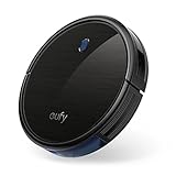


1. Eufy RoboVac 11S
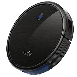
The RoboVac 11S boasts a low profile design at just 2.85-inches thin. This robot vacuum has an anti-scratch tempered glass-top cover for protection and is available in two colors.
Under the hood, the RoboVac 11S packs BoostIQ technology that steps up suction to 1300Pa when extra power is needed. There is a motorized primary brush that agitates and picks up stuck-on dirt from all surfaces and a pair of side sweeping brushes for the wall edges and corners.
When it comes to filtration, the RoboVac 11S has a triple filtration system consisting of a dual-layer filter and one high-performance filter alongside with a 0.6L bin.
Regarding autonomy, the Eufy 11S has a powerful 2600mAh battery that offers 100 minutes in normal mode and around 40 minutes when BoostIQ is active. This robot vacuum will recharge automatically, but it doesn’t resume cleaning automatically. The recharge time is 5-6 hours.
When it comes to navigation and mapping, the Eufy 11S is not the best. The navigation is based on the bounce principle. There are obstacle sensors and drop sensors to prevent accidents. As for mapping, this robot vacuum doesn’t map your home. Instead, it moves in a random pattern. The RoboVac 11S doesn’t have any form of boundary marking.
Last is regarding convenience, and unfortunately, this robot vacuum doesn’t have WiFi. That means it doesn’t offer smartphone app operation or Alexa compatibility. But for its price, this shouldn’t be a concern. The good thing is that it works with a physical IR remote.
2. Yeedi K650 – Best For Carpets
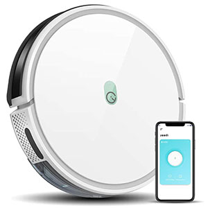
This robot vacuum has a low profile design that is available in white but is not as slim as the Eufy 11S. However, it can still slide under most household furniture, so you won’t have to lift household fittings to allow it to do its job. The Yeedi K650 is available in white.
Under the hood, this robot vacuum packs a powerful 3-speed motor that delivers 600pa in low power mode, 1200 in mid-power, and 2000pa when the max power mode is activated. It is the high suction power that makes it ideal for carpet vacuuming.
Besides the high suction power, this robot comes with a high-speed rotating silicone tangle-free main brush that agitates dirt and picks up pet hair without a problem. It is assisted by dual side brushes that sweep the deep corners and wall edges.
For filtration, there is a triple-filter system that captures up to 99% of allergens and an 0.8L XXL-sized dustbin.
The Yeedi K650 comes with a powerful battery that offers a maximum of 130 minutes runtime in low power mode. When high power mode is activated, the runtime dips. Just like most robot vacuums, this vacuum will dock for recharge automatically, but unfortunately, it doesn’t have the auto-resume function.
When it comes to navigation and mapping, the Yeedi K650 relies on a set of anti-collision sensors to avoid hitting obstacles and anti-drop sensors to keep it off the stairs. As for floor mapping, this robot moves in a random pattern, so it won’t guarantee entire level cleaning. The good thing is that it is compatible with boundary strips for boundary marking, but the strips are to be purchased separately.
Unlike the RoboVac 11S, the Yeedi K650 is a smart home-ready robot vacuum compatible with 2.4GHz WiFi for smartphone app operation. It also supports voice operation and is compatible with voice assistants such as Alexa.
3. ECOVACS Deebot N79S
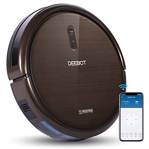
Regarding the design, the Deebot N79S is quite slim at 3.1-inches. It will fit under most low profile furniture, so you don’t have to worry about lifting household stuff or getting stuck under kickstands, sofas, and beds, among other low profile furniture. The Deebot N79S is available in dark brown.
Under the hood, this robot vacuum has a powerful two-speed motor that delivers a maximum of 1000pa when Max mode is activated. There are three cleaning modes; Auto, Edge, and Spot. For agitation and dirt pickup, the Deebot N79S is equipped with a V-shaped bristled brush and two side sweeping brushes. When it comes to filtration, ECOVACS used high-efficiency filters and included a large 0.52L washable bin.
As for autonomy, the Deebot N79S’ 2500mAh battery offers a cool 110 minutes runtime when in normal mode, but when Max mode is active, the runtime is a little bit shorter. This robot will dock at the charging base for recharging, but unfortunately, it won’t resume cleaning automatically.
Just like its cheaper compatriots, the Deebot N79S doesn’t have an intelligent navigation system. It relies on a set of obstacle detection sensors to avoid obstacles though it will hit obstacles in high traffic rooms. There is also a set of anti-drop sensors to prevent falls on the stairs. The robot cleans in a random pattern, but it guarantees entire level cleaning in low traffic and small apartments. Boundary marking is not available.
The Deebot N79S is among the cheapest smart robot vacuums. It supports 2.4GHz WiFi for smart operation via the ECOVACS home app. The robot is also compatible with voice assistants, including Alexa. The robot also works with an IR remote.
4. Coredy R500+ (R550)
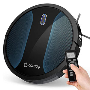
When it comes to the design, the Coredy R500+ boasts a sleek and stylish design. At 2.7-inches, it rivals the RoboVac 11S as one of the slimmest robot vacuums on the market. The top interface is made using anti-scratch tempered glass and is finished in black with blue accents.
Under the hood, the Coredy R500+ packs a 3-point cleaning system. It consists of a powerful motor that delivers a maximum of 1400pa when MAX vacuuming mode is active. There are four other cleaning modes; Spot Cleaning, Edge Cleaning, Manual Cleaning, and Single Room Cleaning. The other components that constitute the 3-stage cleaning system include a V-shaped rubber roller brush with patented tangle-free technology and dual edge-brushes aligned at 27 degrees. When it comes to filtration, this robot vacuum is equipped with a triple-stage filtration system that includes a pre-filter, HEPA filter, and foam filter alongside with a large 0.5L bin.
Next up is the main highlights of this robot vacuum; wet/dry mopping. The Coredy R500+ features a vibrating mopping pad that scrubs all kinds of dirt on bare floors. It’s complemented by a 0.3L water tank that can mop an average apartment satisfactorily.
When it comes to autonomy, the Coredy R500+ comes with a 2600mAh high-capacity li-ion battery that can last it for 120mins per charge. As for power management, the Coredy R550 can recharge automatically, but it won’t resume cleaning until prompted.
While the Coredy R550 packs plenty of features, its navigation and mapping system is not up to the mark. It consists of 12 infrared obstacle detection sensors and pressure-sensitive bumpers. In high traffic rooms, expect it to hit obstacles, while in large apartments, it doesn’t guarantee entire level cleaning as it moves in a random pattern. The good thing about this robot vacuum is that it has boundary marking strips.
Another shortcoming of the R550 is that it’s not a smart robot vacuum as it lacks WiFi. Instead, an IR remote has been supplied. All the same, it’s worth the money.
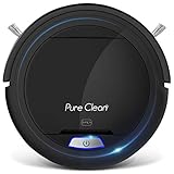
5. SereneLife Pure Clean PUCRC26B V2
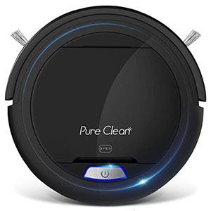
For those looking for a basic robot vacuum, the SereneLife Pure Clean PUCRC26B V2 is a good place to start. It costs just a hundred bucks. You can rely on this robot vacuum to handle light vacuuming needs on bare floors only. It also handles pet hair but not carpets.
The Pure Clean PUCRC26B V2 has a low profile design, standing at just 2.9-inches. It shares the same round shape design as the other robots in this review and is finished in black.
Regarding cleaning performance, this robot offers average cleaning performance. It uses the same 3-stage cleaning system, just like other robot vacuums. In the first stage, the rotating brushes and side sweeping brushes agitate dirt. The dirt is then lifted and sucked into the 0.2L bin. There are also a set of air filters that capture the allergens and dust particles that linger in the atmosphere.
Regarding power management, the Pure Clean PUCRC26B V2 comes with a 1500mAh battery that offers 55 minutes runtime. Here again, there is a lot to be desired, especially if you have large apartments. While it will automatically recharge, the Pure Clean PUCRC26B V2 won’t resume cleaning after getting fully charged.
As a cheap robot vacuum, the PUCRC26B doesn’t have an intelligent navigation system. It, however, has sensors for obstacle detection and preventing it from falling down the stairs. There is no floor mapping, so it cleans in a random pattern and may leave some spots untouched, especially in large apartments with high traffic.
There is not much to expect from this robot vacuum when it comes to smart features and convenience. It doesn’t come with WiFi compatibility, so smartphone operation and Alexa compatibility are not an option. Worse enough, there is no physical remote as the operation is manual using a single button.
6. Tesvor X500 Pro Robot Vacuum Cleaner
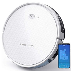
The design of this robot vacuum is pretty standard. It is round-shaped and boasts a low profile design standing at just 2.95-inches. The robot is available in white, with a patterned top interface.
When it comes to cleaning performance, the Tesvor X500 Pro packs a powerful motor that puts up a maximum of 1800pa, making it ideal for bare floors and carpets. The brush system consists of professional bilateral brushes that sweep and agitate all stuck on dirt. Tesvor engineered the X500 Pro with a washable triple filtration system and a 0.6L bin.
Regarding the mopping performance, this robot vacuum comes with a mopping pad and a large water tank for both dry and wet mopping.
Interestingly, the tank has an intelligent system with adjustable water flow for efficiency. Whether it’s the paw marks or urine stains, the Tesvor X500 Pro is ready for the job.
Next up is the autonomy of the Tesvor X500 Pro. This robot vacuum comes with a powerful 2500mAh battery optimized to offer 100 minutes of runtime for continuous cleaning. Like other robot vacuums in this review, Tesvor will recharge automatically, and besides, it will resume cleaning automatically.
The Tesvor X500 Pro excels again in terms of navigation and mapping. The robot vacuum’s 3.0 gyro navigation system guarantees entire level cleaning and fewer accidents. Interestingly, the Tesvor X500 Pro is the only robot vacuum with low price and mapping technology. The robot uses real-time smart mapping that enables it to use efficient S-shaped cleaning patterns and allows homeowners to see the cleaning status of the robot at any time. As for boundary marking, the robot uses magnetic strips to set virtual walls.
Last part is dedicated to smart features and convenience, and once again, Tesvor excels. The robot vacuum works with 2.4GHz WiFi for smartphone app operation and voice assistant compatibility. On the app, users can access all the controls and a wide range of smart features, including over the air (OTA) updates that update the robot vacuum to the latest version of the app. Besides the app operation, the X500 Pro syncs with Alexa for voice operation.
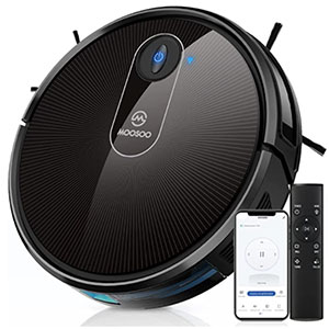
7. MOOSOO MT-720 Robot Vacuum
MOOSOO may be a little-known brand, but it guarantees excellent performance considering its affordable price. The robot is ideal for homes with bare floors, including tile, marble, ceramic, vinyl, laminate, and hardwood, among others. It also handles low to medium pile carpets quite satisfactorily and is unforgiving to pet messes such as pet hair and kitty litter.
The MOOSOO MT-720 boasts a slim 3-inch design to allow it to slide under most of the household fittings. When it comes to aesthetics, the robot vacuum boasts a sleek design and is available in two color options: black and multicolor.
When it comes to cleaning performance, this robot vacuum employs a 3-stage cleaning system where dirt is agitated, lifted, and sucked into the large 0.6L bin. In terms of suction power, this robot vacuum produces a maximum of 1800pa. For the record, there are six cleaning modes; Auto cleaning, Spot cleaning, Edge cleaning, Max vacuum, Plan Cleaning, and Manual cleaning. The brush system consists of a rotating main brush, assisted by two side sweeping brushes.
As for filtration, the MOOSOO MT-720 has a 3-stage filtration system that filters 99% of the fine particles and dust.
Next up is the runtime. The MOOSOO MT-720 comes with a powerful battery that lasts for a cool 120 minutes in low power mode, but of course, in high power modes, the runtime subsidizes. When it comes to power management, the robot will recharge automatically, but it won’t resume cleaning until it is prompted.
Regarding navigation and mapping, the MOOSOO MT-720 is an average robot vacuum with a mix of coveted features. The robot uses anti-collision technology and anti-drop technology, a combination that deploys high-precision sensors to avoid hitting obstacles and falling off the stairs, respectively. While navigation is up to the mark, there is no mapping system, so the robot cleans in a random pattern.
While it is a cheap robot vacuum, the MT-720 comes with all the basic smart and convenient features. It supports both smartphone app and voice assistant operation courtesy of 2.4GHz WiFi. Besides, the company has supplied the unit with a physical IR remote control. So, if you don’t have a stable internet connection, you can still operate the robot vacuum remotely.
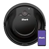
8. Shark ION Robot Vacuum AV751/AV752
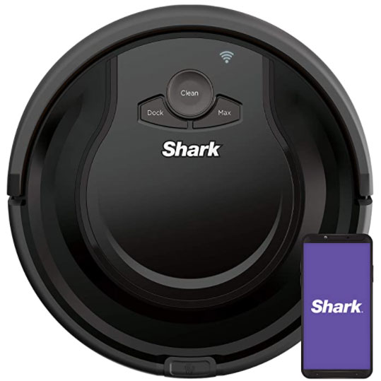
The Shark AV751 and A752 have the same round shape design that most robot vacuums have. It’s not the slimmest robot vacuum in this review, but it will still go under most standard household furniture. The Shark ION Robot Vacuum AV751 has been finished in black, while the AV752 is white.
Under the hood, the Shark ION Robot Vacuum AV751 packs a powerful motor that delivers enough suction power to handle both bare floors as low to medium pile carpets. From our previous tests, the robot vacuum struggled on high pile carpets and Flokati rugs. The brushroll is the same for both models, as well as the side sweeping brushes. They agitate dirt, including stuck-on dirt, and lift them, ready for suction into the 0.6L. Unfortunately, the Shark AV751/AV752 are not self-emptying robot vacuums. If you want a self-emptying robot vacuum from the Massachusetts-based brand, get the Shark IQ RV1001AE.
When it comes to power management, the Shark AV751 and AV752 come with a powerful battery that offers 120 minutes runtime. While most household brands offer auto-recharge and resume, these two robot vacuums will recharge only but won’t resume cleaning until prompted.
While Shark is a household name in the robot vacuum industry, it still limps behind when it comes to navigation and mapping. The big names in the industry use the Visual Simultaneous Localization and Mapping (VSLAM) algorithm, but Shark uses the Simultaneous Localization and Mapping (SLAM) algorithm. It uses sensors to avoid hitting obstacles or falling off the stairs.
The Shark AV751/A752 is a smart robot vacuum that works with 2.4GHz WiFi for smartphone operation and Alexa and Google Assistant compatibility.
9. OKP Life K2
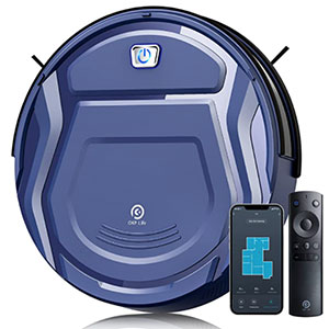
Even though it is not a popular brand, OKP offers excellent value for money with the OKP Life 2. This robot vacuum has been designed for homes with all types of bare floors, including tile, linoleum, vinyl, marble, laminate, hardwood, and ceramic, among others. You can also rely on this robot vacuum to pick up dirt from low to medium-pile carpets. It also comes in handy in homes with pets.
The design of the OKP Life 2 is not different from most of the robot vacuums out there. It maintains the round shape design and is 2.95-inches thin. The low profile design allows it to go under most household fittings, including sofas, kickstands, beds, and other low profile furniture. Regarding the finish, this robot vacuum is blue.
Onto cleaning performance, this robot vacuum uses a 3-stage cleaning system where dirt is agitated, lifted, and then sucked into the 0.5L bin. For the record, there are four cleaning modes: Auto clean, Spot clean, Edge clean, and Manual clean. Under the hood, the robot packs a powerful 3-speed motor that delivers a maximum of 1800pa. You can adjust the suction levels right from the app. The robot vacuum is equipped with a rotating main brush plus dual side sweeping brushes to enable effective scrubbing and dirt pickup.
As for filtration, OKP Life K2 has a high-efficiency filtration system that captures 99% of allergens and dust particles.
Next up is the battery and power management. This robot vacuum features a powerful battery that offers a 70-100 minutes runtime in low power mode, 50-70 minutes in mid, and 30-50 minutes in high power mode. Just like all robot vacuums, OKP Life K2 will dock automatically for recharge, but it won’t resume cleaning automatically.
Regarding the navigation and mapping system, OKP Life K2 may not be the best for large apartments and high traffic rooms, even though the company has taunted the FreeMove Technology 2.0 to be a gamechanger. The robot uses anti-drop technology to prevent it from falling off the stairs and upgraded 6D built-in anti-collision infrared sensors technology to keep it away from obstacles. There is no mapping system, so the robot cleans in a random pattern.
Last is regarding the smart features and convenience. The OKP Life K2 is equipped with 2.4GHz WiFi for remote operation via the smartphone app or Alexa and Google Assistant. Besides app operation and voice assistant compatibility, this robot vacuum comes with an IR remote control.
10. GOOVI by ONSON D380
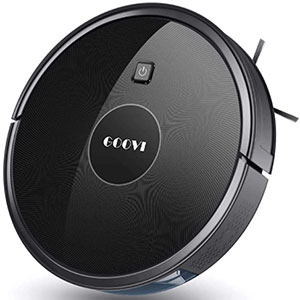
When it comes to the design, the D380 boasts a super slim design. It is 2.83-inches thin, a low profile design allows it to go under most low-profile household furniture like sofas, couches, kickstands, and the rest. The D380 is available in two color options: black on silver and black on gold.
Regarding cleaning performance, the GOOVI D380 relies on the same 3-stage cleaning system that other robot vacuums use. There is a primary brushroll for agitating dirt and 27 ° dual-edge sweeping brushes for the deep corners and wall edges. Under the hood, there is a power motor that puts up 1600pa, which is enough to suck all kinds of dirt on bare floors and low to medium pile carpets. The filtration system consists of a high-efficiency filter and a large 0.6L dust box.
The GOOVI D380 has a reasonable battery life considering its price. It packs a lithium-ion battery that offers 120 minutes runtime. This robot will recharge automatically when the battery goes low, but unfortunately, it won’t resume cleaning without being prompted.
As for the navigation, don’t expect much from this cheap robot vacuum. It uses sensors to avoid falling off the stairs and hitting obstacles. If you have a small apartment with less traffic, it does a great job. But in large apartments with high traffic, it will hit obstacles here and there. The cleaning pattern is random as there is no mapping mechanism. The D380 also lacks any form of containment.
Last is about smart features and convenience. The GOOVI D380 is not a smart robot vacuum. There is no WiFi for smartphone app operation or voice assistant compatibility.
How to Choose the Best Robot Vacuum Cleaner
While our editors might have done all the dirty work for you choosing the best robot vacuum cleaners under $200, you must understand what makes a good robot vacuum. In this section, find out the factors our experts considered when making this list of the best robot vacuums under $200.
1. Low Profile Design
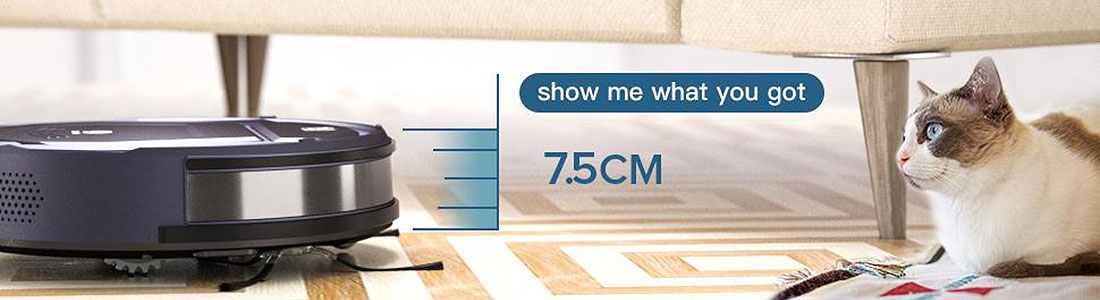
A good robot vacuum cleaner should have a low profile design to creep under most household furniture easily. You don’t want a robot vacuum that will require you to lift some household stuff to get the job done.
Here, the best bang for the buck is the Coredy R500+ which is so far the slimmest robot vacuum we have tested. At 2.7-inches thin, it can go under most low-profile house fittings such as kickstands, couches, sofas, and the rest, without a problem.
2. Cleaning Performance
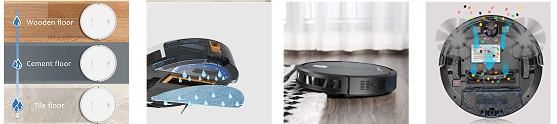
The cleaning performance is the single most important consideration when choosing the best robot vacuum. There are several aspects to consider when talking about cleaning performance.
- The first important thing is the cleaning orientation. There are robot vacuums that sweep and vacuum only, while others will sweep, vacuum and mop simultaneously. Most of the robot vacuums with mopping functions are expensive, but at least Coredy has something for the budget buyers. The Coredy 500 will sweep, vacuum and mop simultaneously.
- The next thing to assess is the application of the robot vacuum. We have robot vacuums for bare floors, robot vacuums for hardwood floors, robot vacuums for carpets, robot vacuums for pet hair, and so on. It’s important to make sure that the particular robot vacuum you are buying suits your cleaning needs.
As far as cleaning performance is concerned, the dilemma is between the Coredy R500+ (R550) vs. Tesvor X500 Pro. These two robot vacuums will vacuum and mop simultaneously. Tesvor carries the day as it has sophisticated mopping features including an electronic water tank that guarantees efficient water usage.
3. Autonomy
Robot vacuums operate using rechargeable batteries. Different battery technologies are used, but lithium-ion is the best choice. This is because they can be recharged many times while remaining stable. Besides the battery technology, it’s essential to go for high-capacity batteries as they translate to longer runtime and, consequently, a larger cleaning area.
Power management is also a concern. While most robot vacuums will recharge automatically, the best bang for the buck is robot vacuums that recharge and resume cleaning automatically.
4. Navigation and Mapping
Another important factor our editors considered when looking for the best robot vacuum cleaner under $200 is the navigation and mapping system. The best shot on the market right now is a robot vacuum with a Visual Simultaneous Localization and Mapping (VSLAM)-based algorithm. Unfortunately, this is a feature that is a reserve for high-end robot vacuums. For a two hundred bucks budget, you can’t get such a robot vacuum.
But at least you can get a robot vacuum with an advanced Simultaneous Localization and Mapping (SLAM)-based algorithm. Besides navigation, mapping is critical. A good robot vacuum should have a mapping system that enables it to clean in a systematic pattern.
Here, the Tesvor X500 Pro is the best deal as it maps your home, guaranteeing entire level cleaning. Another thing under navigation and mapping is boundary marking. Fortunately, most of the robot vacuums in this review have some form of containment measure.
5. Smart Features and Convenience
In this smart home era, you definitely want a smart robot vacuum. Here, the standard is a robot vacuum that supports at least 2.4GHz WiFi. With WiFi, you can operate the robot vacuum remotely via a mobile app. Now, the app features really matter.
Some robot vacuums have more app features than others. From the robot vacuums in this review, the Tesvor X500 Pro is the best deal as it has lots of smart features accessible via the app. Besides the mobile app, you can sync it with voice assistants such as Alexa and Google Assistant. In this review, several robot vacuums support voice assistants. Others go an extra mile to include voice operation and even IR remote controllers.
What’s the Best Robot Vacuum Under $200
Now that we have rounded up the top 10 robot vacuums under $200, it’s time to find out which is the best bang for the buck. As mentioned earlier, robot vacuums are highly specialized. They also vary in prices. That said, it’s hard to say which is the best robot vacuum without assessing the buyer’s needs. In this section, we have highlighted the best robot vacuum under $200 based on the different cleaning needs, buyer tastes, and budget.
If you have bare floors, talk of hardwood tile, ceramic, marble, laminate, and the rest, any robot vacuum will do. Bare floors need a robot vacuum with average suction and a tough main brush to scrub the dirt. Here, you can opt for any robot vacuum in this review. But the best choice will be a robot vacuum with mop. The best option here is, of course, the Tesvor X500 Pro. You can also go for the Coredy R500+ (R550).
When it comes to carpet vacuuming, suction is of great importance, especially when dealing with the high pile carpets and area rugs. That said, you need to buy a robot vacuum with the highest suction power. Here, the best choice is the Yeedi K650 which delivers a whopping 2000pa, which is enough to flush out all the dirt and dust from the deepest parts of your carpet. Other options include the Tesvor X500 Pro, OKP Life K2, and MOOSOO MT-720, which deliver 1800pa.
When looking for the best robot vacuum for pet hair, the considerations are the brush and filtration system. You need to go for a brush that doesn’t get tangled and a filtration system that captures all pet-related allergens. From the robot vacuums we have listed in this review, the Yeedi K650 stands out as it comes with a tangle-free main brush and has a triple-filter system that captures up to 99% of allergens.
If you want the best robot vacuum with low price, all factors considered, the Tesvor X500 Pro is the best deal. It comes with all the bells and whistles that other robot vacuums come with. This is a 2-in-1 robot vacuum cleaner that vacuums and mops simultaneously. With the X500 Pro, you don’t need to spend more money on a dedicated robot mop. This robot vacuum also comes with a mapping function, so it’s ideal for high traffic rooms and large apartments. Another great feature of the Tesvor X500 Pro is the auto-recharge and resume function.


cake carts
Thank you for sharing indeed great looking !